Many years of production experience, high-quality machines
Factory direct sales, welcome to visit the factory
24-hour telephone, email online service.
No installation required, simple operation, support video teaching
| Technical Specifications | HX- 40S |
| Cutting capacity 0° (flat) (length x width) | 0° : 400×510mm
45°: 400×350mm |
| Cutting speed | 33/48/60/84 m/min |
| Saw blade size | 34×1.1×5330mm |
| Main motor power | 4kw-4P |
| Hydraulic motor power | 0.75kw |
| Coolant motor power | 90w |
| Weight(NET WEIGHT) | 1636 kgs |
| Blade guide arm | 690*125*60mm |
| Roller table size | 700*500*610mm |
| Machine dimensions | 2700*1750*1700mm |
| Machine dimensiond (Saw frame raised) | 2700*1750*2070mm |
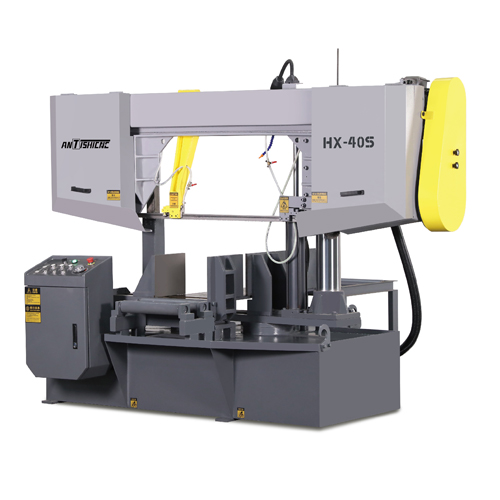
Product Details
This machine is mainly used for sawing small and medium-sized round pipes, square steel pipes, profiles, etc. In addition to 0° sawing, it also has 0-45° rotary sawing.
The feeding adopts hydraulic automatic feeding, automatic length fixing, PLC programmable control, touch screen operation, and grating ruler detects the sawing length. It has the advantages of narrow sawing, material saving, energy saving, high sawing precision, convenient operation and high production efficiency.
Equipment Structure
1.Base:
It is welded by high-quality steel plate, which is used to install the rotating base of the machine tool, lock the T-slot, and work vise. At the same time, the right end of the bottom of the base is the water tank, and the left end is the hydraulic oil tank.
2.Saw frame:
The saw frame is a bow-shaped structure, which is composed of left and right saw frame boxes and beams. The driving wheel, tension wheel, and left and right guide devices are all installed on the saw frame. When the machine tool is working, the saw wheel rotates counterclockwise.
3.The main drive system of the machine tool:
It is composed of a reducer, a driving wheel, and a tensioning wheel. The reducer adopts bevel helical gear reducer, and the speed of the driving wheel is steplessly adjustable through the frequency converter. The tensioning wheel is installed on the left end of the saw frame, and rotates together with the driving wheel after tensioning.
4.Left and right column device:
In order to increase the stability of the machine tool, this machine adopts the cylinder piston rod as the main column, and the cylinder barrel drives the saw frame to move up and down. In order to increase the stability of the saw frame, an auxiliary column is designed at the left end of the saw frame, and the auxiliary column adopts a small cylinder.
5.Saw belt guide device:
The guide of this machine tool is divided into two parts: movable guide arm and fixed guide arm. The fixed guide arm is installed on the left side of the saw frame, and the movable guide arm can be manually moved on the dovetail plate of the cross beam of the saw frame, and the distance between the guide arms is determined according to the width of the sawing workpiece. After adjustment, lock the guide arm. There is also a pre-guide to ensure stability.
6.Saw belt tensioning device:
In order to make the machine work normally, the band saw blade must be tensioned to a suitable tension. The saw blade is tensioned by a torque wrench, and the tension slider is driven by a thread rod to move the saw wheel to the left, and the saw blade is tensioned, and the tension is set by the torque wrench.
7.Vise clamping device:
The clamping pressure of the workpiece is clamped by a hydraulic vise, the oil cylinder adopts the screw oil cylinder method, and the clamping stroke of the oil cylinder is 50mm. When clamping, first move the movable vise to about 20mm away from the workpiece through the screw rod, and then activate the clamping button to clamp the workpiece. The workpiece must be clamped when sawing.
8.Cooling system:
In order to prolong the service life of the saw blade, prevent the saw blade from heating, ensure the sawing accuracy, improve the quality of the sawing surface, and prevent the sawing surface from rusting. The machine tool adopts a cooling pump for centralized cooling, the cooling water is circulated, and the coolant is saponified liquid.
9.Hydraulic system:
This machine tool adopts a separate hydraulic station, which is located on the left side of the machine tool and consists of hydraulic oil tank, oil pump, solenoid valve, etc. In order to prevent heat generation, the hydraulic oil cooling adopts a fan to cool the return oil of the oil pump relief valve. The descending speed of the saw frame is adjusted steplessly by the speed regulating valve, which is suitable for sawing of different materials.
10.The automatic adjustment device for the feed amount of the saw frame:
It is installed above the fixed guide head, and a throttle valve is installed, which is in contact with the fixed end guide head through a mandrel. When the feed of the saw frame is too large, the saw belt will be very The large thrust pushes the guide head upward, reduces the opening of the throttle valve through the ejector rod, and slows down the descending speed of the saw frame to ensure that the sawing process does not pull the teeth and prolong the service life of the saw belt.
11.Electrical system:
This machine tool adopts an independent electrical operation control cabinet, all electrical components are installed in the electrical cabinet, and the power circuit of the machine tool is 380V/50Hz. All actions of the machine tool are controlled by PLC, and the traditional button operation is replaced by a touch screen. The speed of the saw belt, the feeding times and the feeding length can be set on the touch screen, and the feeding times and length can be set in 5 groups at the same time.
User friendly.
12.Feeding device:
Automatic feeding is adopted for the feeding of the machine tool. The feeding vise moves along the circular guide rail for feeding under the push of the hydraulic cylinder. The single feeding stroke is 400 mm. The detection of the feeding length is measured by the grating ruler. The feeding tolerance is within±0.2 mm.
13.Angle rotation device:
The rotation of the machine tool angle is driven by a hydraulic cylinder, and the angle measurement is controlled by a rotary encoder.
Driven by the hydraulic cylinder, the rotary seat rotates around the rotation center, and the rotary encoder automatically calculates the rotation angle. When the specified angle is reached, the saw frame stops rotating, and the angle locking oil cylinder locks the rotary seat in the T-slot to prevent sawing. Displacement during cutting causes angular deviation. The rotation angle can be set and displayed on the touch screen.
14.Spiral chip conveyor:
In order to reduce the labor intensity of the operator, the machine tool designs a helical chip conveyor to output sawdust out of the machine tool.
Main Parts for the saw machine
| Main Configuration Schedule | ||
| NO. | Name | Brand |
| 1 | Main motor | CHINA |
| 2 | Hydraulic motor | CHINA |
| 3 | Water pump motor | CHINA |
| 4 | Solenoid | CHINA |
| 5 | Transformer | CHINA |
| 6 | Alternating current contactor | CHINA |
| 7 | Thermal Overload Relay | CHINA |
| 8 | Contact Relay | CHINA |
| 9 | Miniature Circuit Breaker | CHINA |
| 10 | Switch Push buttons | CHINA |
Remark:The accessories in the configuration list allow the manufacturer to change the accessory brand to a higher level according to the material supply. Users can purchase other brand accessories according to their needs.
Standard Equipment
Main Saw machine body
Hydraulic system
Saw frame automatic adjustment equipment
Feeding device
Angle rotation device
Cooling system
Spiral chip conveyor
Operator manual
Optional Parts and Optional Equipment
| NO. | Spare parts Description | Specification | Function |
| 1 | detachable rack | 2 meter | Take the load of materials |
| 2 | Pressure reducing valve | Clamping force regulation at Hydraulic station | Adjustable vise pressure (suitable for cutting thin-walled tubes) |
| 3 | Saw blades | 34×1.1×5330 mm | Consumable cutting parts |
Youtube Channel : Antishicnc Machine